
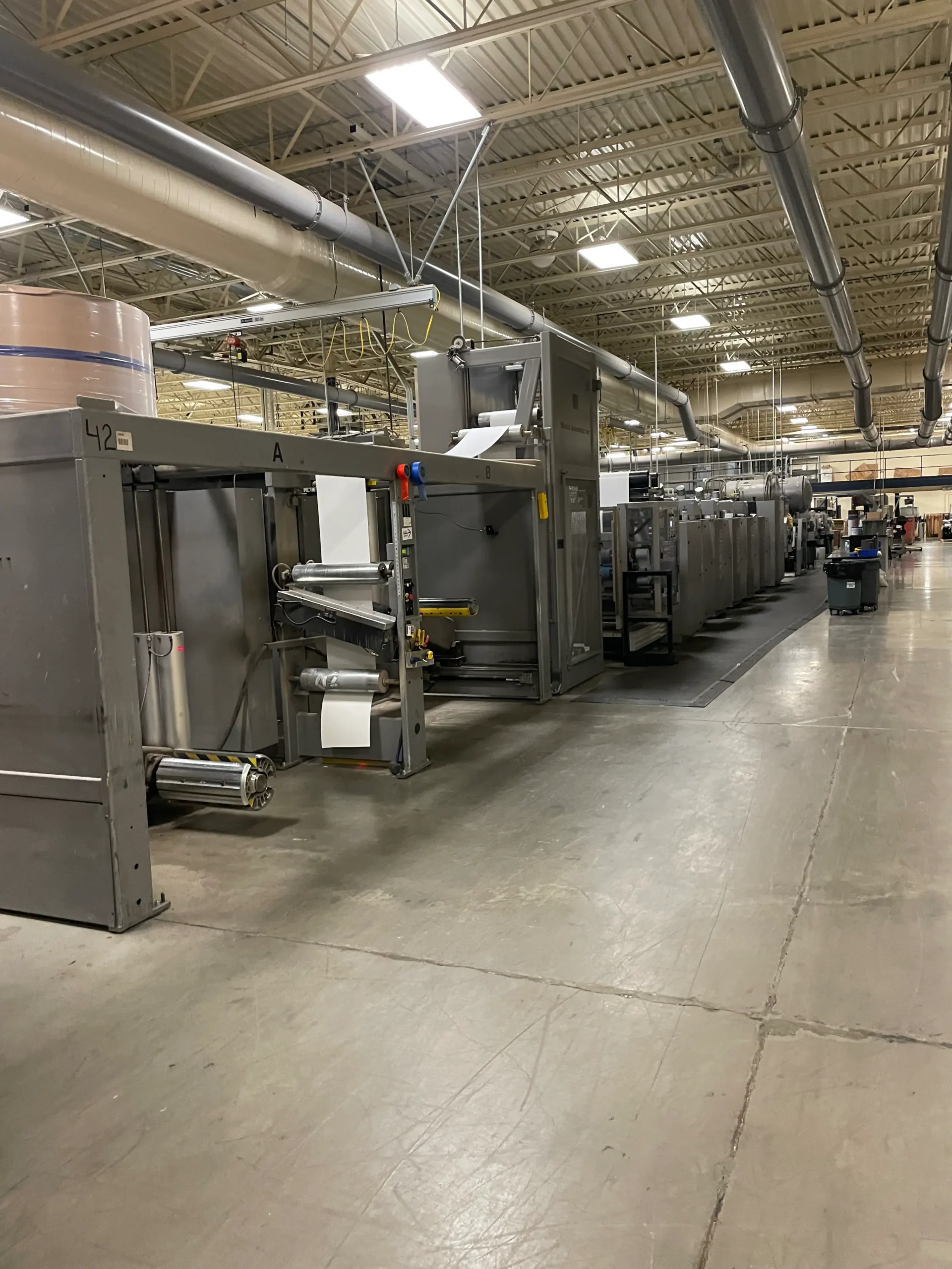
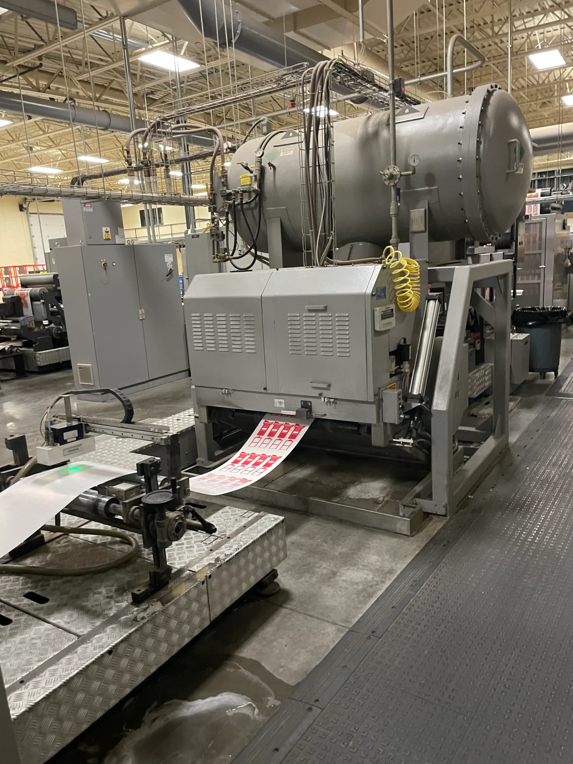
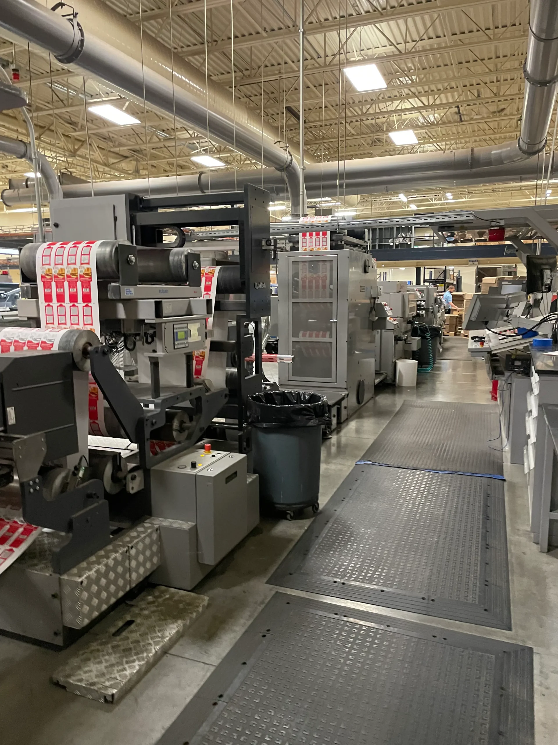
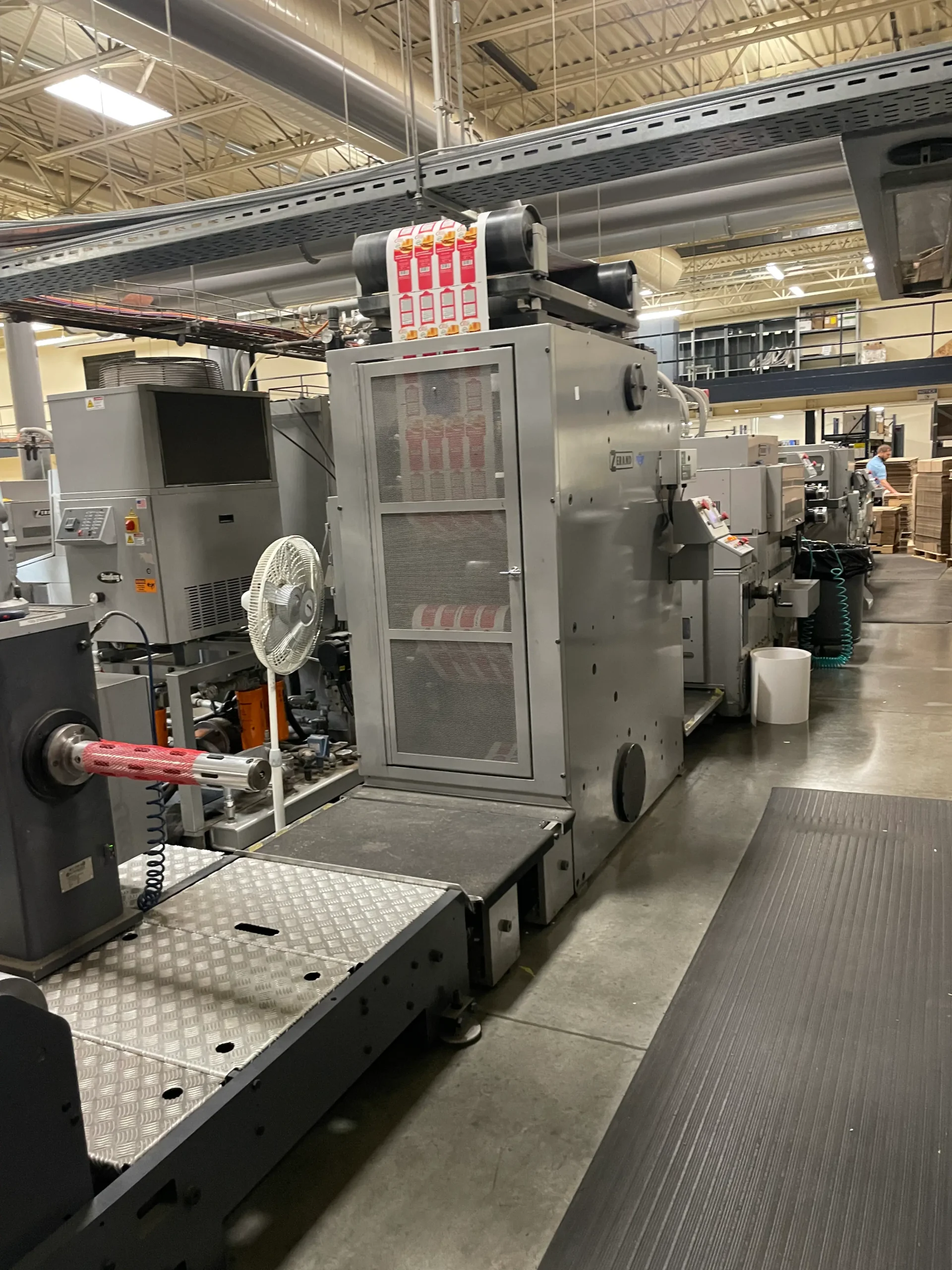
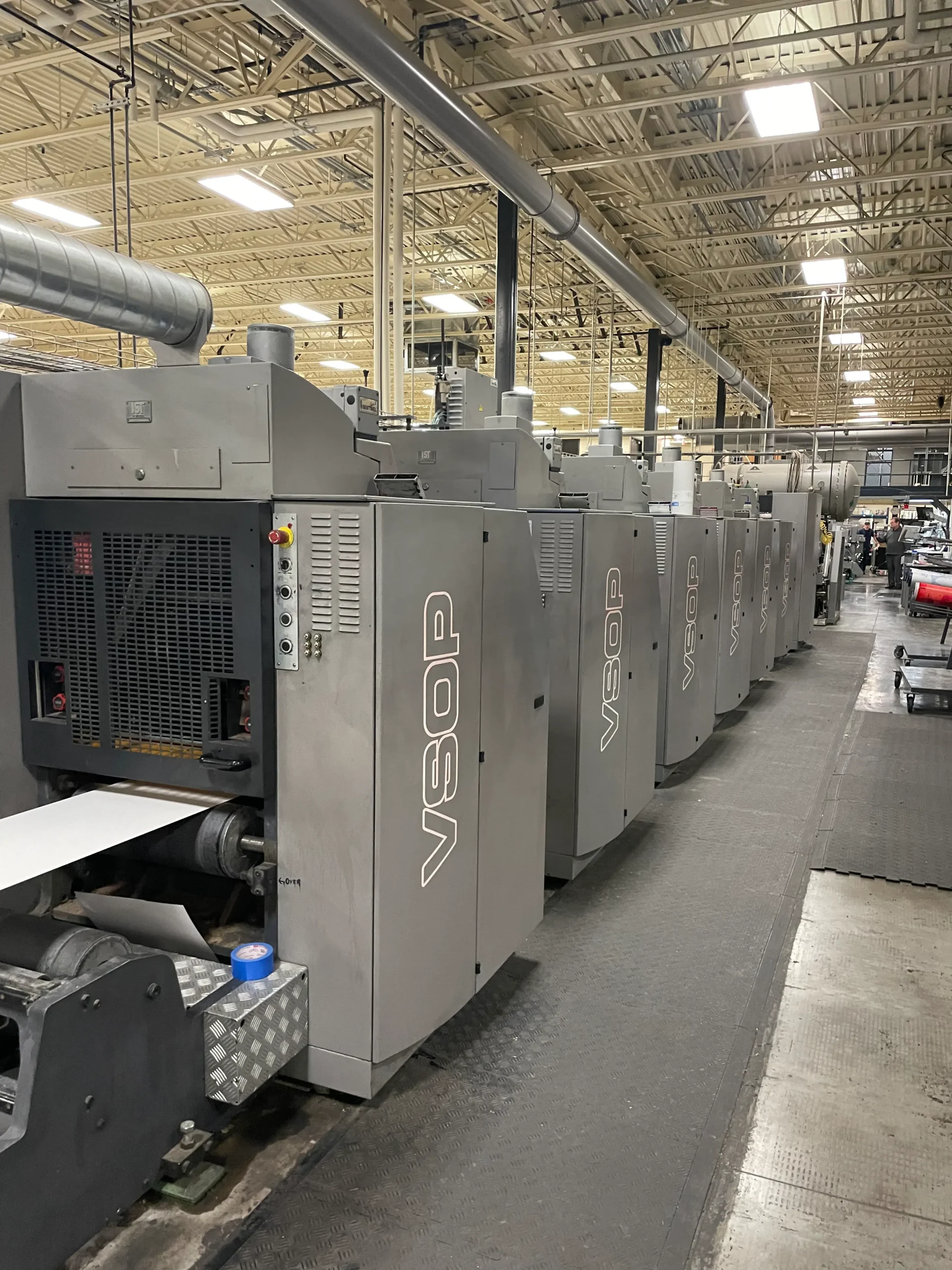
Mueller Martini Variable Sleeve Offset Press
Type VSOP-520, Specifications, 2012 install
20.5” maximum web width
Materials paperboard .010” to Paperboard .028”
Maximum print repeat 30”
5 offset print units
1 Flexo print unit with Tresu enclosed ink chamber and diaphragm pumps
Martin Unwind, MBX 10-22-72, automatic butt splicer
ESI Down Firing EXCURE 1 EB Dryer
Rewinder for test printing
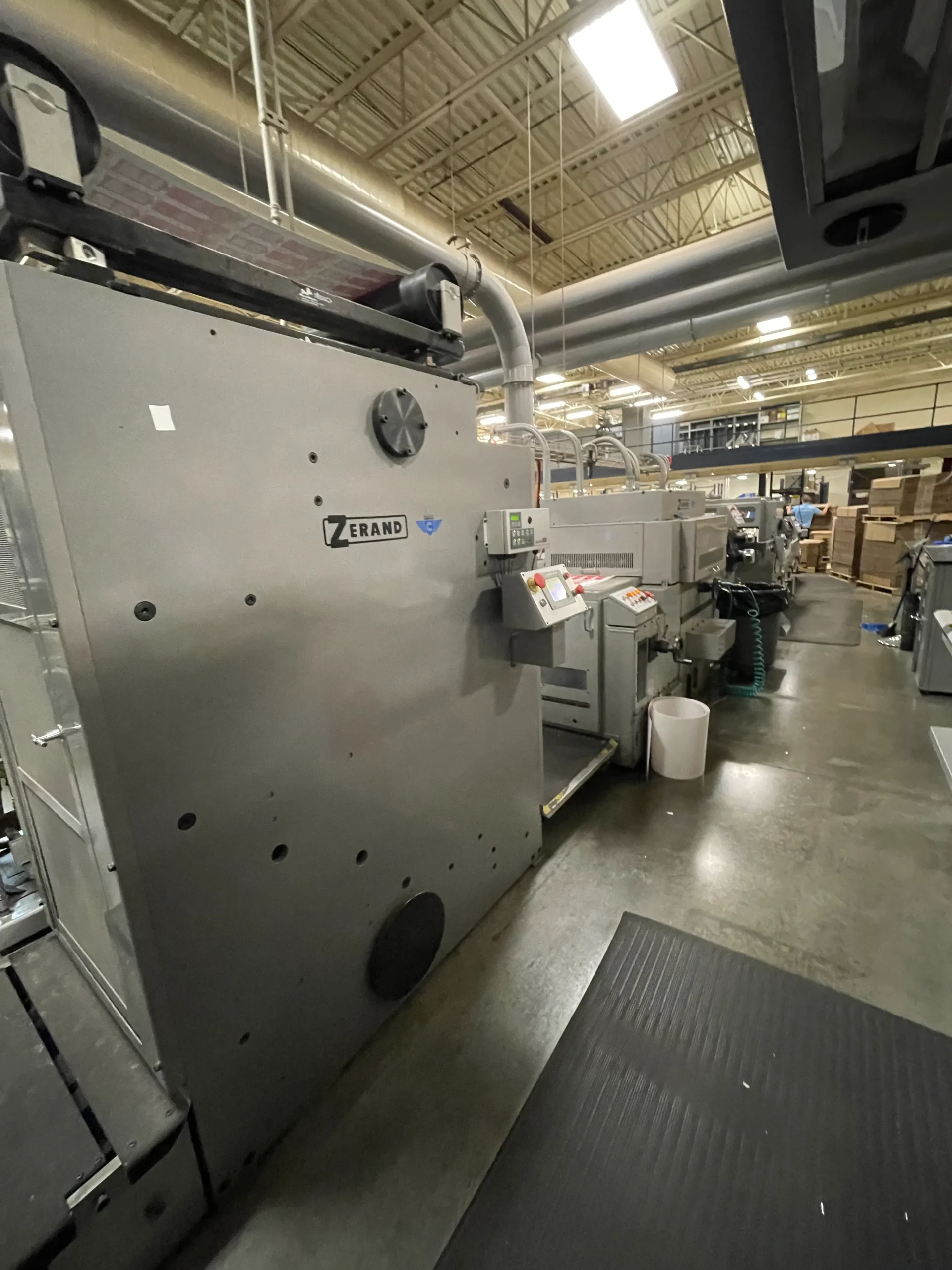
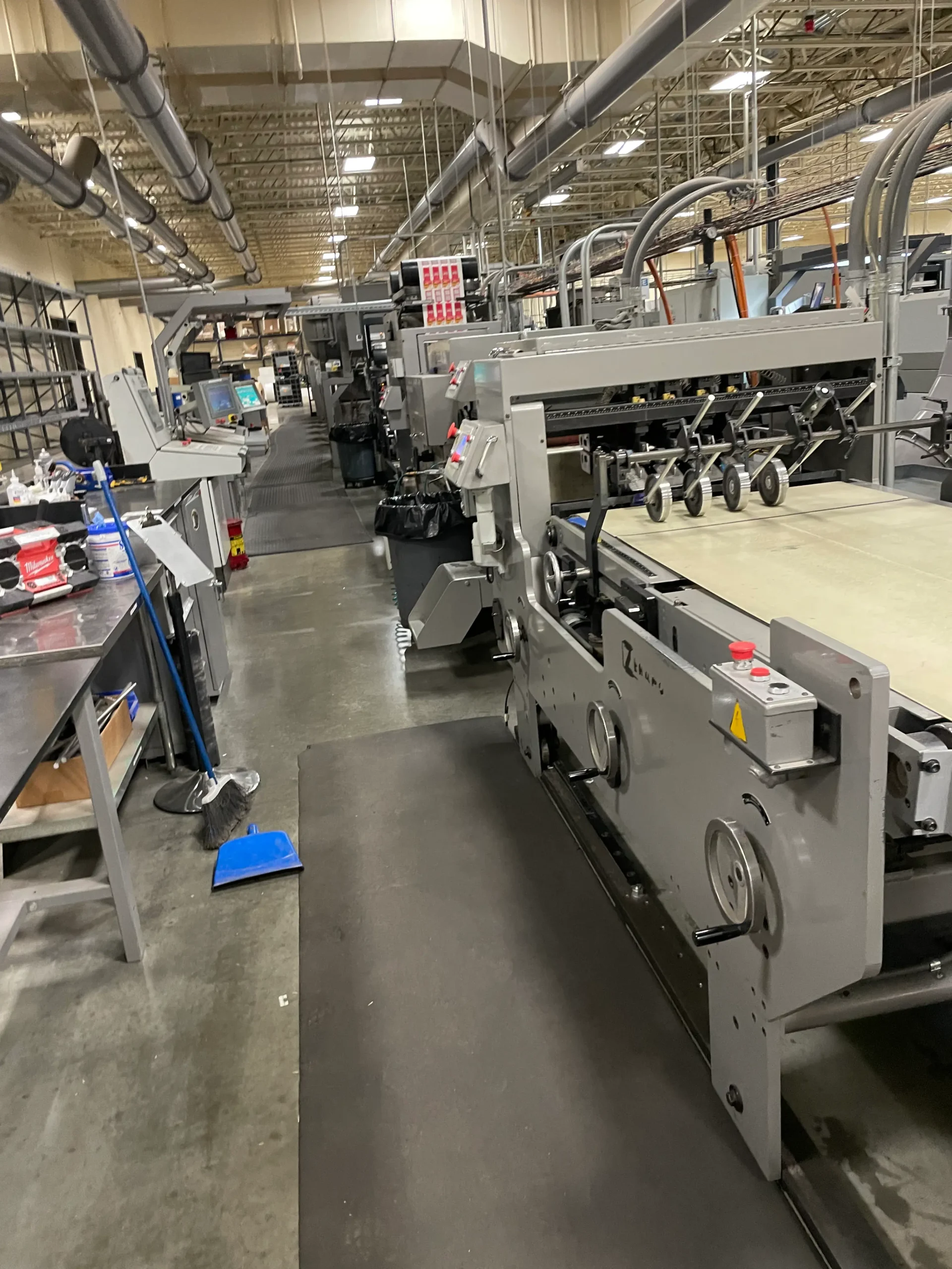
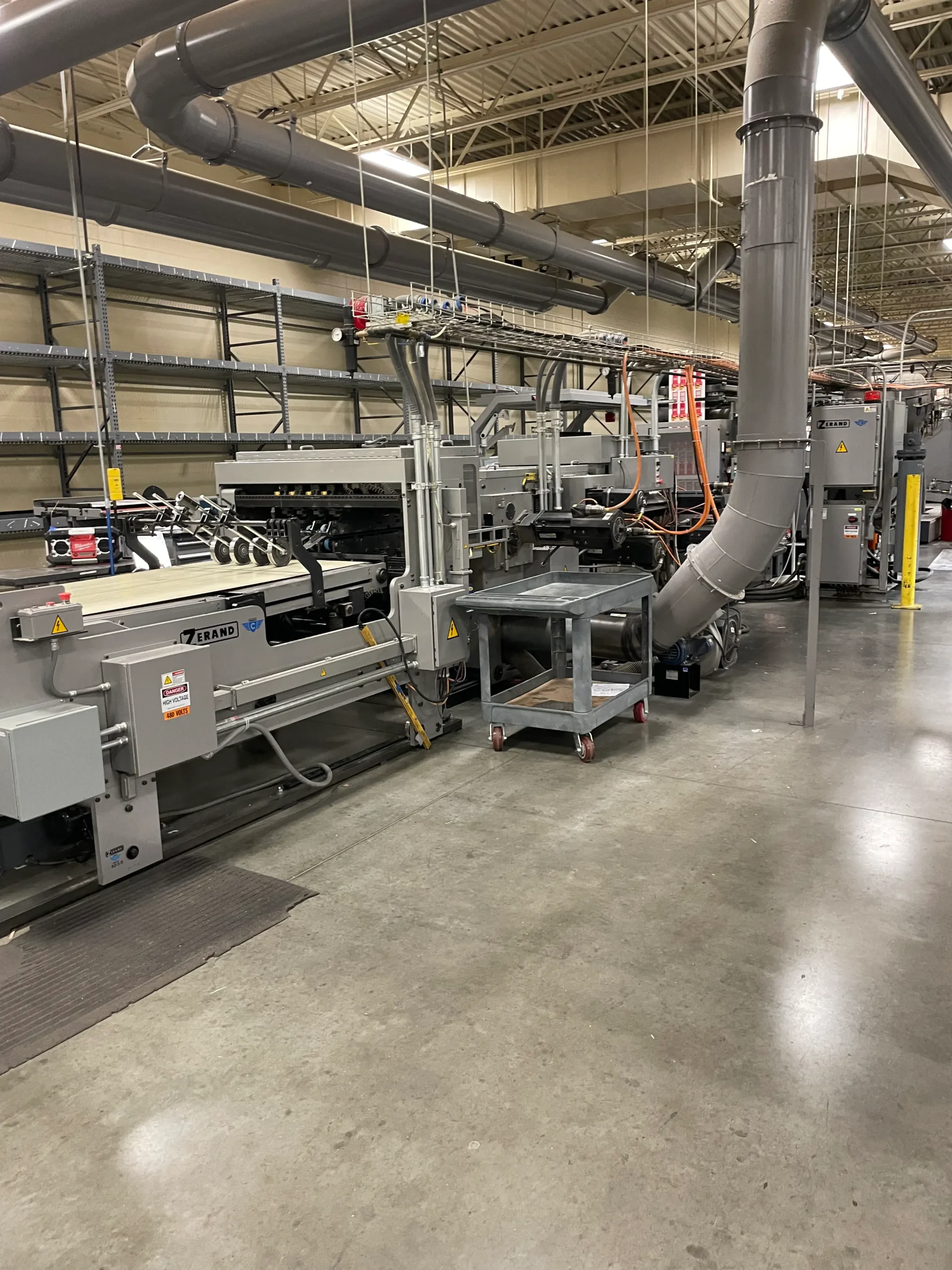
Electronic interface to Zerand 22” ELS Platen Die Cutter, ELS Stripper and 32”
Combination Belt Skew Delivery Table
Accuweb Wide Away web center guide at infeed and outfeed
Polymag CCR Web Cleaner, nip to nip design
5 IST Ink Mist Hoods
5 Sentinal Ink Dispensers
Technotrans Apha. D Dampening
Floclear Filtering System
Technotrans Delta.Z Temperature Control
Baldwin Blanket Washing
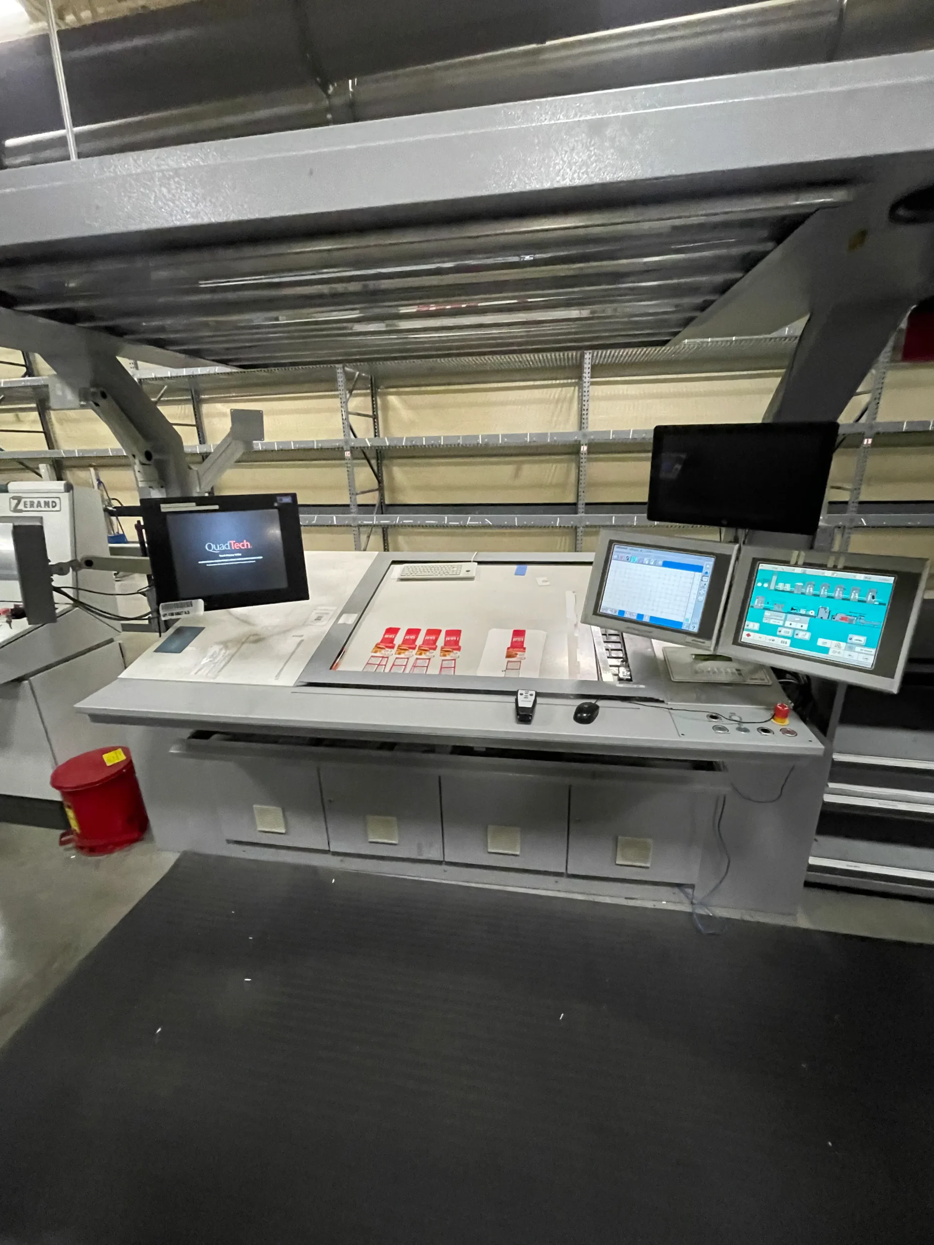
Eltromat OFFCON 4 Register Control System and Ink Fountain Control
BST Super Handy Scan 4100 web Viewing System, New 2020
Quad Closed Loop Color Control
Main Control Console
CIPCON
5 Complete Sets of New Rollers.
5 Complete Sets of Used Rollers
Print Stations Rebuilt in 2016
Press Control PC Upgrade to Windows 10, New 2022, DG Services
Press has been covered by yearly service agreement with DG Services
Miscellaneous Spare Parts, list is available
Wide Range of Plant and Blanket Sleeves, list is available
Large Inventory of Zerand Tooling, list is available
Plate Bender, Plate Trimmer and Plate Mounting Stand
Plate/Blanket Sleeve Carts
2.1 ONE (1) DRENT OFFSET PRESS – Supplied By Others
NOTE: The press supplier must have an outfeed unit prior to the post press decurl to
control the tension on the press up to that point and insure that the web is delivered to the
post press decurl with a tension variation not to exceed + 3 pounds.
2.2 ONE (1) POST PRESS DECURL UNIT WITH DANCER
The Post Press Decurl Unit is used to control the amount of web curl in the board just prior to
going into the cutter. This unit is used for final control of curl with immediate results. This
faster reaction to board curl enables better operator-thus reducing the possibility of carton
jamming.
Motorized decurl bars controlled by push buttons from unit and delivery section
3/4″ (19.1 mm) decurl bars
Decurl wrap control idlers
Rapid “retum lo center” upon activation of a push button
Web guide (BST) with auto edge guide
Air Loaded Dancer
2.3 ONE (1) ELS PLATEN DIE CUTTER CREASER UNIT
The Cutter Creaser is a platen type-reciprocating unit in which the printed web is die cut and
creased into a specific carton form. The unit includes two sub sections – the metering section and
the platen section. The metering section includes a metering nip, intermittent feed nip and
moving curved plate assembly designed to place exactly the same amount of web into the cutting
area each impression of the cutter creaser.
Maximum operational speeds to 700 FPM or 350 impressions per minute, whichever is less
Cut-off maximum 30″ (762 mm) – minimum 15″ (381 mm)
Cutting and creasing loads to 400,000 lbs.
Maximum Cutting/Creasing Rule 725″ (18,415 mm)
100% control of web into cutter during entire cycle
Low inertia moving curved plate contacting bottom side of web
Rigid steel upper and lower platens
Lower platen pull down springs
Self lubrication system
Three point support of each crankshaft
External heating and cooling system for controlling lubricating oil operating temperature
Electronic batch counter
Refrigeration System for controlling feed roll surface temperature
Two (2) die chases
Two (2) counter plates
Auto set-up as in Item 2.8
Special: Scanner modification, same as previously done on Z-1030.
2.3 ONE (1) ELS PLATEN DIE CUTTER CREASER UNIT – Continued
ZWW-1998-R0
November 4, 2009
Page S of 18
Servo Driven Lower Feed Roll
The ELS (Elcctrically Line Shafted) Feed Roll system drives the lower feed roll with a
rigidly coupled servo drive system. The motion of the lower feed roll is controlled digitally
by calculating the optimum velocity profile for a given printed repeat length at any given
production speed, within the ratings of the cutter. The primary function of the lower feed
drive system is to minimize the speed differential between the web and the driving lower
feed roll while maintaining control of the web. The lower feed roll is specially designed for
operation with the drive system to reduce the overall roll and system inertia while
maintaining liquid cooling capabilities for the lower feed roll and the servo motor.
operator simply inputs the repeat length of the printed carton and the system automatically
calculates the optimum performance for the system.
Servo Driven Metering Roll
The ELS (Electrically Line Shafted) Metering Roll systen drives the metering roll with a
reducer and servo drive system. The ELS Metering Roll drive system provides accurate
metering roll control for web feed and registration control. The operator will simply input
the repeat length of the die layout and the system will automatically feed up the correct
amount of web per cycle of the cutter. The system will also provide integration for a print to
cut registration system.
NOTE: Poly coated (backside) substrate may be run on the cutter, speed may vary
depending on the substrate.
2.4 ONE (1) NORTH AMERICAN CERUTTI, ZERAND DIVISION PRINT TO CUT
REGISTER SYSTEM
The North American Cerutti, Zerand Division print to cut registration is integrated in the
equipment servo control system to allow the highest level of response.
A commercially available color registration scanner is used to detect the cutter registration mark.
The system makes automatic adjustments to the repeat length as web and print variations enter
the cutter over a long term.
The system makes automatic corrections for instantaneous variations of the print to cut
registration position.
NOTE: Registration expectations: # .006″ 98% of the time, to the key color, under steady
state running conditions. Registration is based of the mechanical integrity in the previous
operation and the printed mark. Variations in the consistency of the printed mark will
have an effect on the print to cut expectations.
Z W W- 1 9 9 8 – R 0
November 4, 2009
Page 6 of 18
2.5 ONE (1) ELS STRIPPER UNIT
The Stripper’s function is to remove all of the waste from the carton patterns before the carton
blanks are separated by the delivery unit.
The Electronically Line Shafted (ELS) Stripper uses two servo (vector) motors to drive the
reciprocating nip cam and the pin cylinder. Each is timed to the platen die cutter position. The
reciprocating nip timing and pin cylinder angular position may be adjusted while the platen die
cutter is running or while stationary. Pin cylinder position may also be adjusted manually to
compensate for cut form phase changes as line speed is increased and/or decreased. Displays are
provided for pin cylinder and nip timing relative to the platen die cutter allowing the user to
reduce make ready time. Both motors are synchronized to the position of the platen die cutter
through a main reference encoder mounted on the cutter.
100% Stripping of carton waste
3/8″ minimum scrap target
High speed stripper nip rolls
Positive pin register adjustment – machine direction and across machine
Infinite stripper pin locations
Air loading of the upper and lower incoming nips
Air loaded chucking of the anvil roll and pin cylinder with air retraction
Two (2) pin cylinders
Two hundred (200) stripping pin assemblies
One (1) anvil roll
Auto set-up as in Item 2.8
2.6 ONE (1) SCRAP REMOVAL SYSTEM
Scrap hopper
Booster fan and motor
Electrical controls for booster fan
Ducting, trim handling fan and motor supplied by customer
2.7 ONE (1) 32″ COMBINATION BELT SKEW DELIVERY
The purpose of the belt askew unit is to separate the cut and stripped form, both in the running and
cross machine direction, into individual cartons suitable for shingled delivery to the attached
delivery table.
Belt controlled askew of cartons
Scale reference for repeating jobs
Automatic speed following design
Rail mounted for ease of movement
Equipped with four (4) streams
NOTE: A stream consists of one (1) upper and one (1) lower belt assembly.
2.8 ONE (1) ELECTRIC DRIVE SYSTEM – INDRAMAT
ZWW-1998-R0
November 4, 2009
Page 7 of 18
Minimum 40 HP Cutter motor
AC supply voltage to be nominal per customer requirement
Control circuits 110 volt AC
Control power to be OFF when main power is OFF
ICC electrical cabinet – Must be located within 100 cable feet to any motor. Recommended
installation is on the drive side
Control Console for Cutter Controls – mounted on Cutter
Auto Setup with Touch Screen for Cutter and Stripper to store up to 1,000 jobs.
The touch screen running the auto setup interface software will be able to return to any
previous settings by simply selecting the job number of the stored location and initiating
the auto setup cycle. Where settings are manual, the system stores set-up references.
NOTE: The press drive must be compatible with North American Cerutti, Zerand
Division’s drive.
2.9 LINE ELECTRIC’S – (North American Cerutti, Zerand Division Equipment Only)
2.10 LINE ENGINEERING – North American Cerutti, Zerand Division Equipment
Only)
2.11 ONE (1) DOCUMENTATION PACKAGE
Three (3) sets, Installation Drawings
Three (3) Operating Manuals – in electronic media only